The topics addressed and contents of this paper were written based upon student-submitted papers for the GNSS Accuracy Assignment, as part of the AGT 1007 Electronics and Control Systems course, fall semester 2020.
In today’s precision agriculture world, GPS is at the core of many of the most common applications of this technology. From machine guidance and auto-steering, to variable rate application of inputs based on the location within the field, to mapping harvest yields, GPS is vital to achieving the desired outcomes of utilizing these systems.
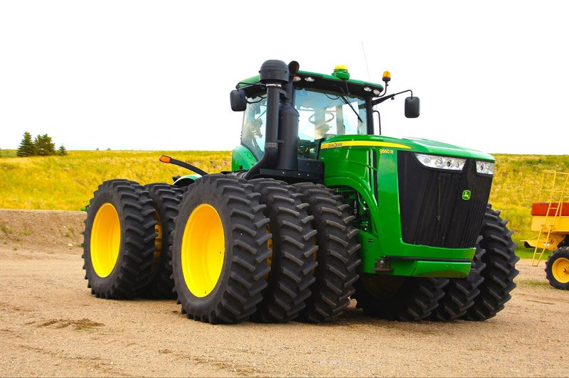
Figure 1: John Deere tractor with StarFire GNSS Antenna
Source: Madereugeneandrew (https://commons.wikimedia.org/wiki/File:John_Deere,_9560R.jpg), https://creativecommons.org/licenses/by-sa/4.0/legalcode
So what is GPS? GPS stands for Global Positioning System, and refers to the constellation of GPS satellites launched by the United States Department of Defence that began in 1978. By 1993, the complete GPS satellite system, consisting of 24 satellites became fully operational1. Today there are 28 operational satellites in the GPS constellation2.The initial purpose of GPS was to provide the US military with a robust navigation system that would allow personnel to know their position virtually anywhere on the planet, and the most accurate satellite signals were reserved for US military users only. Since 2000, civilian users also have access to these higher accuracy signals, and today’s dual frequency GPS receivers (as found in most current precision agriculture hardware) make use of both the L1 and L2 satellite bandwidths.
GPS isn’t the only satellite constellation today however. In fact, there are multiple additional constellations, many of which also provide global coverage. GLONASS, the Russian satellite navigation constellation is perhaps the most well known here in Canada because it provides increased satellites in view in the northern skies. This has greatly benefitted many agricultural users in northern latitudes that used to experience down-time when not enough GPS satellites were available for high accuracy position calculations. Notable others include BeiDou, the new Chinese constellation, and Galileo from the European Space Agency, both of which also provide global coverage. The term GNSS (Global Navigation Satellite System) refers to all of these constellations, not just GPS, and therefore today’s modern receivers should be referred to as GNSS receivers rather than GPS receivers, because they are capable of utilizing satellite signals from multiple constellations.
GNSS accuracy is an important consideration for all agricultural users. For some tasks, high accuracy may be less important, but for others it may be critical. Agricultural users therefore need to determine the acceptable accuracy level(s) for their requirements. Often this is a balancing act between cost and performance to achieve the optimum return on investment for a given application. For example a tractor used primarily for tillage may not require such high accuracy GNSS input into an auto-steering system as a tractor pulling a seeder that will perform inter-row seeding (placing seed accurately between the stubble rows left by the previous year’s crop).
GNSS receivers compute their position by measuring how long it takes for signals from different satellites to reach the receiver. Each satellite signal contains a message that tells the receiver exactly when the signal was broadcast by the satellite, as well as the position of the satellite in orbit at the time of transmission. Using a complex mathematical modeling process, the GNSS receiver attempts to compute the distance between it and the satellite based on the time taken to receive the signal. Modern dual frequency GNSS receivers repeat this process a second time as they also receive a second signal from each satellite. Once a minimum of 4 satellite signals are being received, the receiver can compute it’s position on the earth based on triangulation of it’s position in relation to each satellite.
The accuracy of GNSS is affected by numerous factors, the largest of which is atmospheric interference, as signals pass through space and into the earth’s atmosphere. An example of how the atmosphere can disrupt and delay satellite signals from different satellites is shown in Figure 2. Therefore, without accounting for these errors, we would see significant inaccuracies in the computed positions. While dual frequency receivers are able to account for some of the error by comparing the time taken for two signals on two different wavelengths to be received, they still cannot achieve the kinds of accuracies often needed for precision agriculture applications.
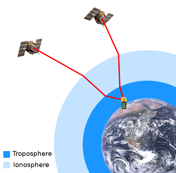
Figure 2: Atmospheric interference on GNSS satellite signals
Source: The Earth seen from Apollo 17.jpg: NASA Navstar-2.jpg: NASA GPS tracking satellites.jpg: Vaughan Weather derivative work: Javiersanp (talk) (https://commons.wikimedia.org/wiki/File:Gps-atmospheric-efects.png), Gps-atmospheric-efects“, https://creativecommons.org/licenses/by-sa/3.0/legalcode
The solution to achieving very high accuracy GNSS positioning is to correct the computed positions using information from ground-based reference stations. A reference station is essentially simply another GNSS receiver, but it is installed at a fixed and known location. It receives the same satellite signals as a nearby user, and computes its position in the same way. Because the reference station knows its true position (because it has been programmed with it), it can then calculate how much error has occurred in the computed position. For example, if the station computes its position as being 1m west and 0.5m north of it’s known true position, we now have a correction that could be applied to other users in the vicinity and we can tell them to adjust by the same amount.
This is, in simple terms, how GNSS corrections work, and how we can achieve much greater accuracy than simply allowing GNSS receivers to compute their positions autonomously (i.e. without using any form of corrections).
Essentially, GNSS corrections fall into two categories; free and paid. Commercial options may require purchase of specific hardware, unlocks, subscriptions, or a combination of all of these. It also stands to reason that the free corrections will not be as accurate as paid corrections. But there are also several levels of available accuracy with paid corrections and commercial hardware. Let’s take a look at what’s available:
These virtual correction messages are continually broadcast every second so the rover is constantly receiving updated corrections just like it would with a radio RTK system. The resulting accuracies are typically equivalent to radio RTK, without the need to purchase or operate a base station. This has made VRS RTK the preferred choice of professional land surveyors and engineering surveyors because they can achieve survey-grade accuracies within minutes of arriving on-site without the need to set up and calibrate base stations. The major limitation to VRS is the reliance on cellular data coverage to receive the corrections, which can be a real issue in many parts of Western Canada, for example. VRS is also only available in select regions where the required ground-based reference stations are located.
First year students on the new Precision Agriculture - Techgronomy Diploma course wanted to find out how real-world accuracy compares to the claimed accuracies of some GNSS corrections. For our testing we utilised a Trimble TMX-2050 precision agriculture display with integrated GNSS receiver. This display (as just about any other from all manufacturers) offers SBAS (WAAS) corrections as a standard feature, while activations and/or subscriptions are required to unlock the ability to use higher accuracies.
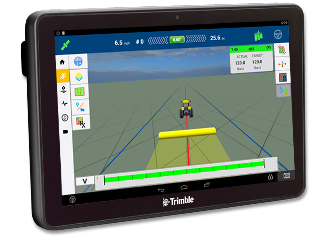
Figure 3: A Trimble TMX-2050 Display
Source: TMX-2050™ Display System (2020), Trimble, [online] available at https://agriculture.trimble.com/product/tmx-2050-display/
The TMX-2050 can be programmed (provided it has the required activations and subscriptions) to operate autonomously (i.e. with no corrections applied), or using one of the following corrections:
For our testing we were able to test the accuracy of the receiver using the following correction methods:
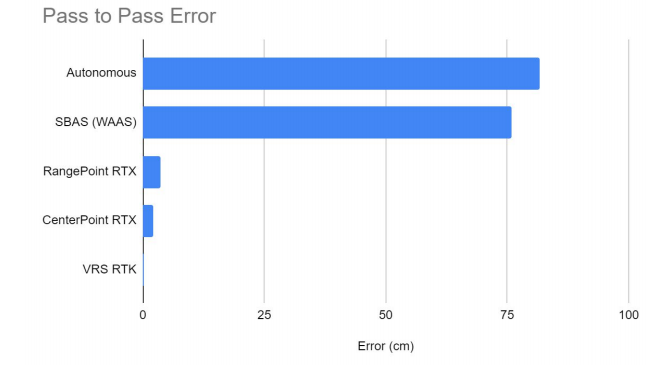
 We wanted to test the accuracy of each correction method in real-time as well as over a period of approximately 15-30 minutes. This would allow us to model both the real-time fluctuations we might expect to see as a machine drove up and down the field (which may present as deviations in the steering direction, for example) as well as pass-to-pass accuracy. Pass-to-pass accuracy is an important consideration because drift often occurs in GNSS position over time. As satellite geometries change throughout the day, computed positions may also change, and the effect is typically more pronounced with lower-accuracy systems. Most manufacturers use a 15-20 minute time period to report pass-to-pass accuracy, as this relates to average time taken to drive a single pass up or down the field. If you had a GNSS that experienced a position shift of one foot over a 15 minute period, you may see overlap or underlap of up to one foot by the time you reach the end of each swath. Depending on the operation being performed, this may not be desirable.
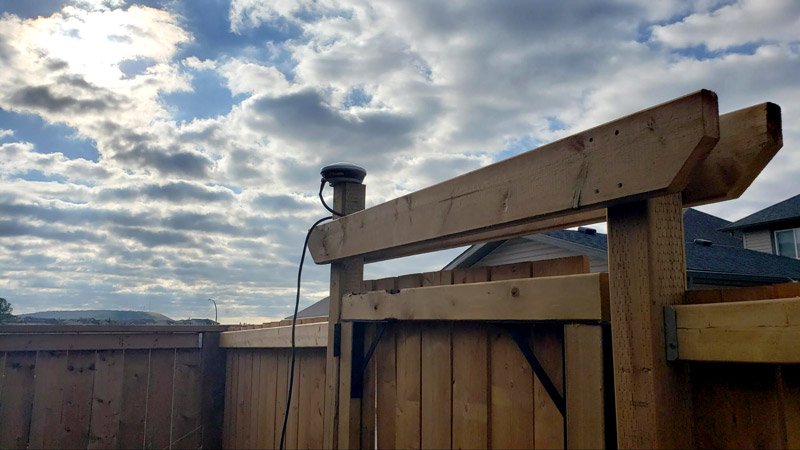
The TMX-2050 was attached to a Trimble Ag25 GNSS antenna. The antenna was placed in a fixed position on top of a post approximately 2.25m above ground level. It should be noted that due to Covid-19 travel constraints the test was performed in a residential setting, with some potential for nearby buildings to interfere with satellite signals. This however, could be compared to a challenging farm environment where there may be nearby trees, hills, or structures that equipment would be expected to operate around.
Figure 3: GNSS antenna in fixed position for testing. Source: Photograph by Simon Knutson
By placing the antenna in a fixed location and recording positional data once per second, we were able to analyse the data and model the positional changes reported both over a short period of time (approximately one minute) and compare average reported positions over a 15-30 minute period (representing pass-to-pass accuracy).
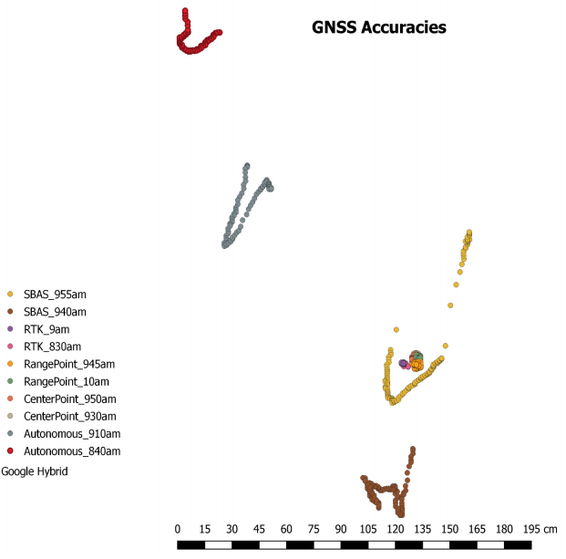
Assuming the GNSS position calculations were perfectly accurate, and because the antenna didn’t move, all of the data points measured should fall exactly on top of one another and we shouldn’t be able to distinguish between them. However, we know that GNSS positions, and in particular the lower accuracy correction methods, are likely to exhibit significant differences in reported positions, and this is what we were looking to measure.
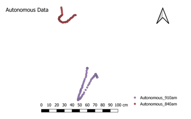
Figure 4: Positional drift in autonomous GNSS positions
Source: Dagenais, I (2020). GNSS Accuracy and Corrections [unpublished manuscript]. Olds College
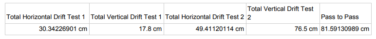
Figure 5: Autonomous GNSS positioning accuracy summaries
Source: Grattidge, D (2020). GNSS (GPS) Accuracy Comparison [unpublished manuscript]. Olds College
As illustrated in Figures 4 and 5, we measured significant short-term drift in autonomous position over both test periods. This would likely present as noticable steering adjustments and driving lines that are noticeably not perfectly straight. The differences in average positions reported in the two tests (approximately 30 minutes apart) also illustrate that we would be likely to experience significant pass-to-pass position shifts, and this would result in potentially close to 1m of underlap or overlap.
Perhaps surprisingly, we did not measure significantly improved precision with WAAS corrections applied to the GNSS position. As shown in Figures 6 and 7, there was still a significant positional drift, particularly in the second test that was not significantly less than our autonomous test. The two tests are grouped slightly closer together, suggesting that pass-to-pass accuracy may be slightly improved versus autonomous positioning.
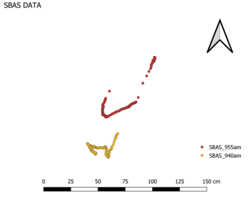
Figure 6: Positional drift in SBAS GNSS positions
Source: Dagenais, I (2020). GNSS Accuracy and Corrections [unpublished manuscript]. Olds College
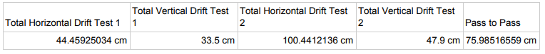
Figure 7: SBAS GNSS positioning accuracy summaries
Source: Grattidge, D (2020). GNSS (GPS) Accuracy Comparison [unpublished manuscript]. Olds College
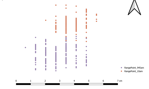
Figure 8: Positional drift in RangePoint RTX GNSS positions
Source: Dagenais, I (2020). GNSS Accuracy and Corrections [unpublished manuscript]. Olds College
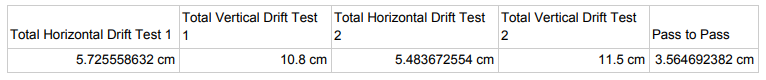
Figure 9: RangePoint RTX GNSS positioning accuracy summaries
Source: Grattidge, D (2020). GNSS (GPS) Accuracy Comparison [unpublished manuscript]. Olds College
Both real-time precision and pass-to-pass accuracy were significantly improved in the RangePoint RTX corrected positions, as illustrated in Figures 8 and 9. This level of accuracy was actually unexpected, as it significantly exceeds published specifications. Therefore we cannot conclude that this level of accuracy will always be achievable, but based on our testing, this correction would certainly be suitable for the applications Trimble suggests, such as most broad-acre farming needs.
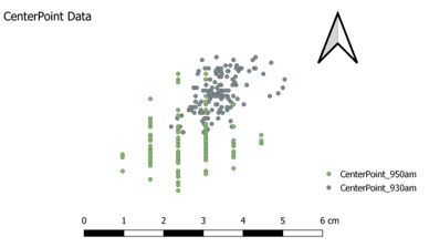
Figure 10: Positional drift in CenterPoint RTX GNSS positions
Source: Dagenais, I (2020). GNSS Accuracy and Corrections [unpublished manuscript]. Olds College
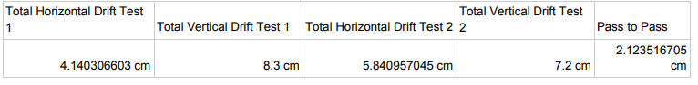
Figure 11: CenterPoint RTX GNSS positioning accuracy summaries
Source: Grattidge, D (2020). GNSS (GPS) Accuracy Comparison [unpublished manuscript]. Olds College
As expected, CenterPoint RTX proved more precise and accurate than RangePoint RTX, but not as significantly as may be expected. In both tests, but the second test in particular, we saw slightly more positional drift than the advertised accuracy figures would support. When we averaged the positions from each test, the pass-to-pass accuracy was very good, and matches the published values. Vertical accuracies were shown to be unsuitable for most water management tasks.
Figure 12: Positional drift in CenterPoint VRS (RTK) GNSS positions
Source: Dagenais, I (2020). GNSS Accuracy and Corrections [unpublished manuscript]. Olds College
Figure 13: CenterPoint VRS GNSS positioning accuracy summaries
Source: Grattidge, D (2020). GNSS (GPS) Accuracy Comparison [unpublished manuscript]. Olds College
Also as expected, the VRS corrections were validated as providing the highest accuracies. Overall drift within each test was minimal, and although there were several outliers in the first test we still did not see more than 3.8cm of position change. Pass-to-pass accuracy here was very good, and exceeded published specifications. Vertical accuracy was also very good, making this a suitable correction method for water management applications.
Based on our findings, the consensus among the students is clear that a mid-accuracy correction such as RangePoint RTX offers the best balance between affordability and accuracy for most precision farming tasks. Our test results confirmed that RangePoint RTX is likely to exceed the published accuracy levels, and with it’s more affordable subscription cost combined with it not requiring any additional paid activations in the GNSS receiver, it represents excellent value and performance.
For tasks requiring the highest accuracies, CenterPoint VRS is the clear winner. But this comes with a higher subscription cost, plus a requirement to add paid activations to the GNSS receiver in order to utilize RTK corrections. It also relies on good cellular data to operate, so this may make it unrealistic for many western Canadian farms.
For the increased subscription costs, plus the additional paid hardware activation required, CenterPoint RTX showed a modest improvement over RangePoint in our testing. For a farm looking for the highest accuracy without the cost and potential headaches of RTK this was shown to be a good option, particularly for larger farms that could not cover all of their landbase with a single RTK base station, or where cellular reception for VRS is an issue.
We plan to expand on this project in the future to include additional brands and corrections available in the precision agriculture marketplace - stay tuned!
Global Positioning System History (2017), NASA, [online] available at https://www.nasa.gov/directorates/heo/scan/communications/policy/GPS_History.html
Frequently Asked Questions (2020) GPS.gov, [online] available at https://www.gps.gov/support/faq/#sats
WAAS Ground Segment (2018), ESA Navipedia, [online] available at https://gssc.esa.int/navipedia/index.php/WAAS_Ground_Segment
StarFire (navigation system) (2020), Wikipedia, [online] available at
StarFire™ 6000 with SF1 Receiver (2020), John Deere, [online] available at https://www.deere.com/en/technology-products/precision-ag-technology/guidance/starfire-6000-receiver/
OmniSTAR (2020), Wikipedia, [online] available at https://en.wikipedia.org/wiki/OmniSTAR
StarFire™ 6000 with SF3 Receiver (2020), John Deere, [online] available at https://www.deere.com/en/technology-products/precision-ag-technology/guidance/starfire-6000-receiver-with-sf3/https://en.wikipedia.org/wiki/StarFire_(navigation_system)
Trimble RTX Frequently Asked Questions (2020), Trimble Inc, [PDF document] available at https://positioningservices.trimble.com/wp-content/uploads/2019/02/Trimble-RTX-FAQ-2020-Brochure.pdf
The topics addressed and contents of this paper were based upon a summary of all student-submitted papers from the GNSS Accuracy Assignment, as part of the AGT 1007 Electronics and Control Systems course, fall semester 2020.
Submitted by Simon Knutson, Agriculture Technology Instructor, Olds College - November 2020